Empowering AI Data Computing Breakthroughs: Hynetek Unveils Quarter-Brick High-Efficiency Power Supply Reference Design
10 24, 2025
As processor core performance increases, coupled with the growing adoption of 54 V low-voltage DC architectures in traditional AI data centers, handling megawatt-level cabinet power leads to significant resistive losses due to excessive current. This necessitates thicker copper cables and higher material consumption, posing challenges in both economic viability and practical implementation. To address this, NVIDIA proposes transitioning to an 800 VDC direct current power distribution system. This new architecture shifts from traditional 415 VAC or 480 VAC alternating current to building an end-to-end 800 VDC DC bus. It eliminates redundant AC-to-DC conversion stages, delivering high-voltage direct current directly to compute nodes. This approach not only significantly reduces transmission losses but also saves up to 26% in space compared to traditional multi-stage conversion solutions.
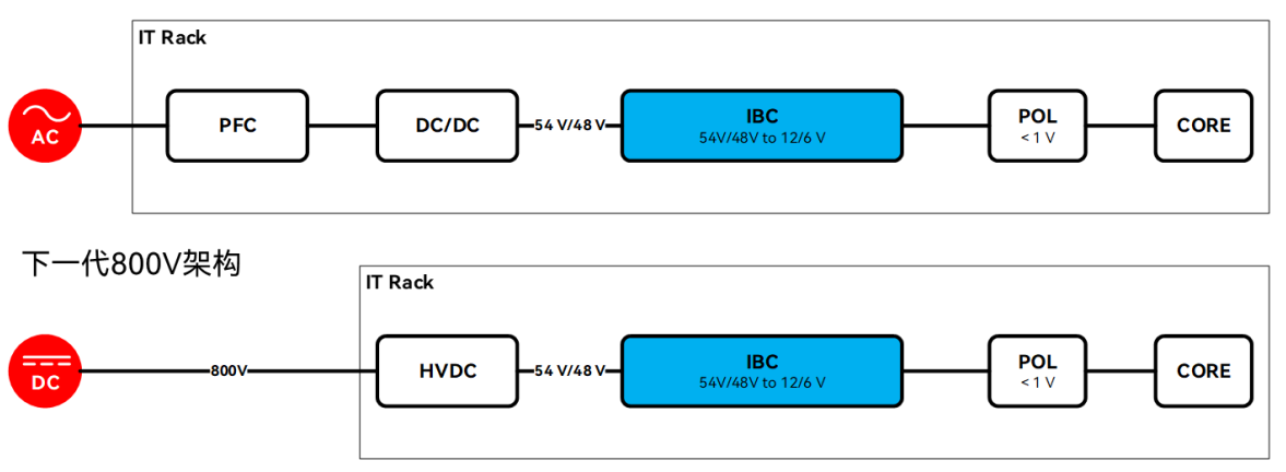
Figure 1: Data Center Computing Power Architecture
In the hierarchical power architecture of data centers, the intermediate bus converter (IBC) plays a pivotal bridging role: it converts the 48 V DC power supplied from the front end (such as UPS) into a lower intermediate bus voltage (e.g., 12 V or 6 V). This voltage serves as the input for point-of-load (POL) converters, which ultimately deliver precise and stable voltages to specific chips like CPUs and ASICs. The power rating and physical dimensions of IBCs have become standardized, exemplified by the common 1/4-brick package. Targeting this standard form factor, Hynetek has developed an efficient 1/4-brick power reference design centered around its HP1000 multi-function DC-DC digital power controller. This demonstrates the chip's application potential in optimizing power density and efficiency.
Traditional power supply development often faces four major pain points: limited space, low efficiency, long development cycles, and diverse requirements. Engineers must repeatedly debug circuit parameters to meet power demands across different scenarios while spending significant time debugging software code. Even more troublesome is the need to build additional metering circuits and write data acquisition code for real-time monitoring of power output. Any misstep can lead to project delays or even increased R&D costs. The HP1000 brick module power supply reference design, engineered specifically to address these industry pain points, has officially debuted. With core advantages of “no coding required, plug-and-play functionality, high efficiency and reliability, and flexible adaptability,” plus built-in power metering capabilities that simplify power monitoring, it serves as an “all-in-one assistant” for engineers. The HP1000's 4 mm x 4 mm QFN-24L package enables compatible designs with the XDPP1100-Q024, XDPP1140-100B, and XDPP1148-100B.
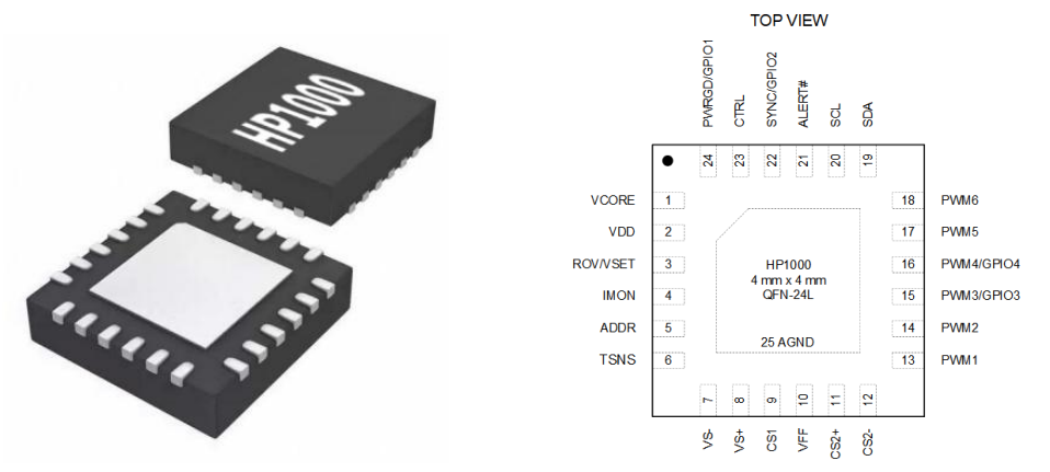
Figure 2: HP1000 QFN-24L Package and Pinout Diagram
HP1000 Chip Features
Multifunctional digital controller, supporting various 48V input isolated and non-isolated topologies
Compliant with PMBus Revision 1.2 communication interface, supporting PEC and custom extension commands
Up to 6 programmable PWM outputs, 312.5 ps equivalent resolution
Programmable switching frequency range from 50 kHz to 1 MHz
50 MHz high-speed voltage-sampling ADC and 25 MHz high-speed current-sampling ADC
High-Performance Loop Control
4 programmable general-purpose I/O pins
Rich, diverse, and flexible fault detection and protection mechanisms
Compatible with DOSA standard analog voltage regulation
Programming through an intuitive graphical user interface (GUI)
The basic parameters of the HP1000 600 W quarter-brick module full-bridge converter reference design are as follows:
Input Voltage: 42 ~ 75 VDC
Output Voltage: 12 VDC
Output Current: 50 A
Output Power: 600 W
Switching Frequency: 265 kHz
Peak Efficiency: 96.3% (30 A)
Full-Load Efficiency: 95.7% (50 A)
Power Supply Dimensions: 58.4 mm x 36.8 mm x 12.7 mm
HP1000 600 W Quarter-Brick Module Full-Bridge Converter Reference Design Physical Diagram is shown below:
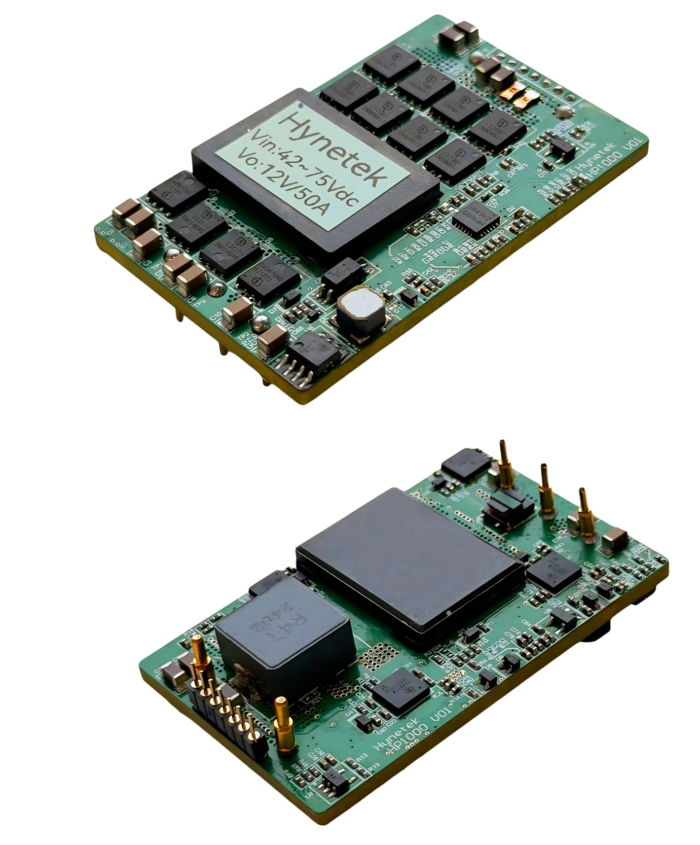
Figure 3: Actual photo of the Hynetek 600 W quarter-brick modular power supply
Designing a 600W 1/4 brick module power supply using the HP1000 chip: Four core advantages to solve power supply design challenges.
1. Full-scenario compatibility, adapt to requirements without writing code
The HP1000 features an extensive array of built-in configuration options, supporting multiple PWM output types, timing configurations, loop settings, output voltage adjustments, operating frequencies, duty cycles, dead zones, protection points, and protection modes. Whether powering industrial control modules or delivering stable power to core equipment in communication base stations, engineers need not develop driver code or control programs from scratch. Simply configure parameters via the intuitive GUI based on actual requirements to rapidly integrate settings into the HP1000 chip, significantly reducing repetitive development time and financial costs.
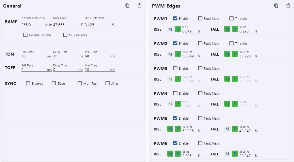
Figure 4: PWM Configuration Interface
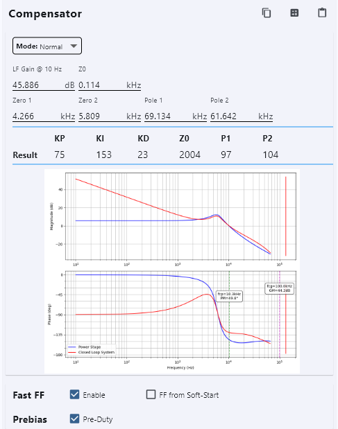
Figure 5: Loop Configuration Interface
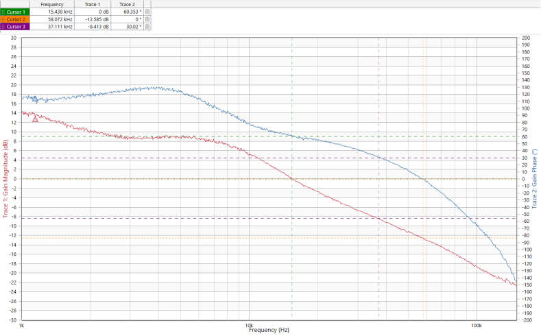
Figure 6: Loop Test Curve: Phase +60 degrees, Gain -12.6 dB
2. Built-in multiple protections ensure stable system operation
The reliability of the power supply directly determines the safety and lifespan of the entire system. This 1/4-brick modular power supply reference design incorporates multiple protection mechanisms, including input under-voltage, input over-voltage, input over-current, transformer saturation (secondary-side short-circuit), output over-voltage (including single-point over-voltage from feedback pin shorted to ground), output over-current, over-temperature, and output short-circuit. Upon detecting abnormal operating conditions, it rapidly activates protection functions to prevent damage to the module and downstream equipment.
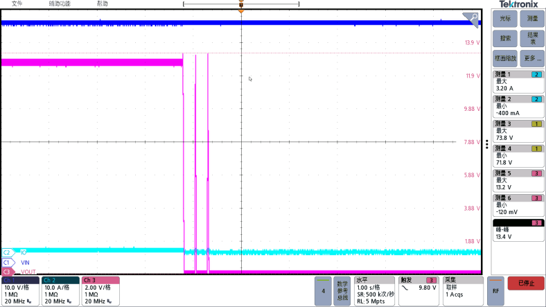
Figure 7: Measured Output Overvoltage Protection Waveform (Configured with 13 V Overvoltage and Secondary Restart)
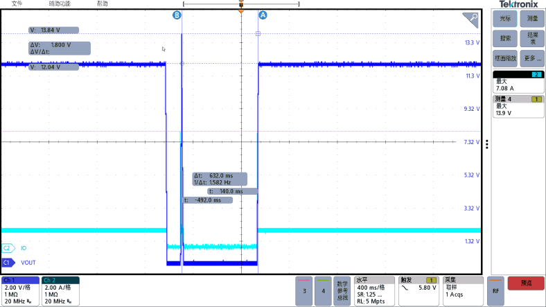
Figure 8: Measured overvoltage waveform at the short-circuit feedback pin output (maximum output 13.9 V)
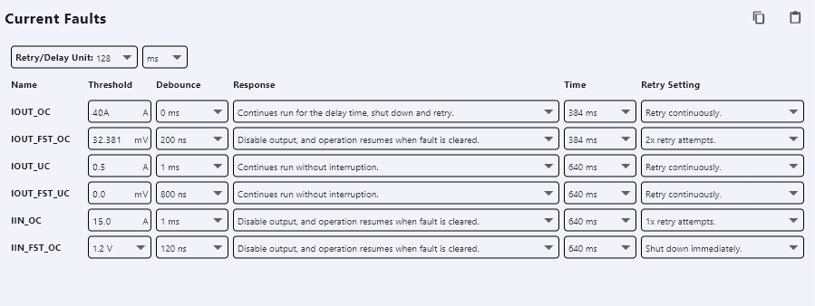
Figure 9: Current Protection Configuration Interface (Configure 40 A Overcurrent and Disconnect)
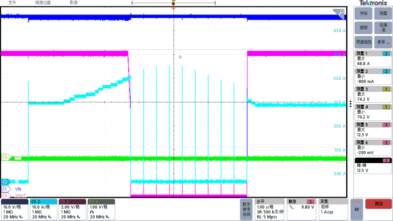
Figure 10: Measured Output Overcurrent Protection Waveform (Disconnect Protection Triggered at 41 A Output Current)
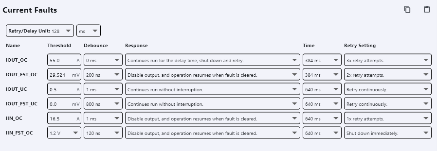
Figure 11: Current Protection Configuration Interface (Configured for 55 A Overcurrent and 3 Restarts)
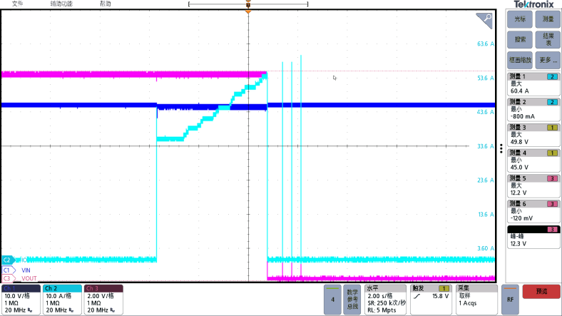
Figure 12: Measured Output Overcurrent Protection Waveform (Protection triggered at 56A output current, followed by standby after three restarts)
3. Built-in power metering, allowing real-time monitoring of power status without coding
The HP1000 chip also features built-in high-precision power metering capabilities, enabling this 600 W brick module reference design to achieve high-accuracy power measurement without requiring any additional coding or external power metering hardware! The HP1000 integrates metering functions and data processing circuits internally, allowing real-time acquisition of critical parameters such as input/output voltage, current, power, and energy consumption. After calibration, it achieves accuracy within ±1%. Engineers need not build separate metering modules or develop data acquisition programs. Simply connect a display or computer via the I2C interface to intuitively read real-time data through a GUI. Alternatively, integrate directly into the device control system for automatic power data upload and monitoring.
Whether it's precisely monitoring battery charge and discharge power in new energy storage projects or real-time control of load power consumption in industrial automation equipment, this feature eliminates the need for cumbersome code development and circuit construction, enabling one-step power monitoring.
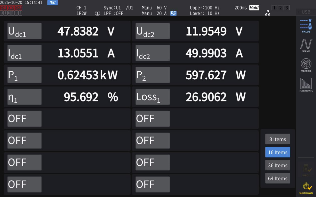
Figure 13: Measured input and output data
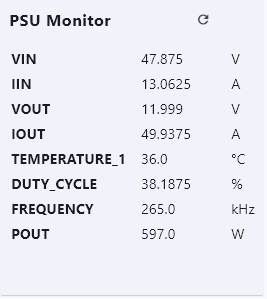
Figure 14: Real-time Monitoring of Power Metering Data
4. High density and high conversion efficiency, reducing energy consumption
Within the 42 V to 75 V input voltage range, conversion efficiency reaches up to 96.3%. Compared to traditional designs, this not only significantly reduces energy consumption losses but also minimizes heat generation—meaning engineers no longer need to agonize over thermal solutions. Whether for compact devices or high-power applications, it adapts effortlessly, indirectly shortening the overall R&D cycle.
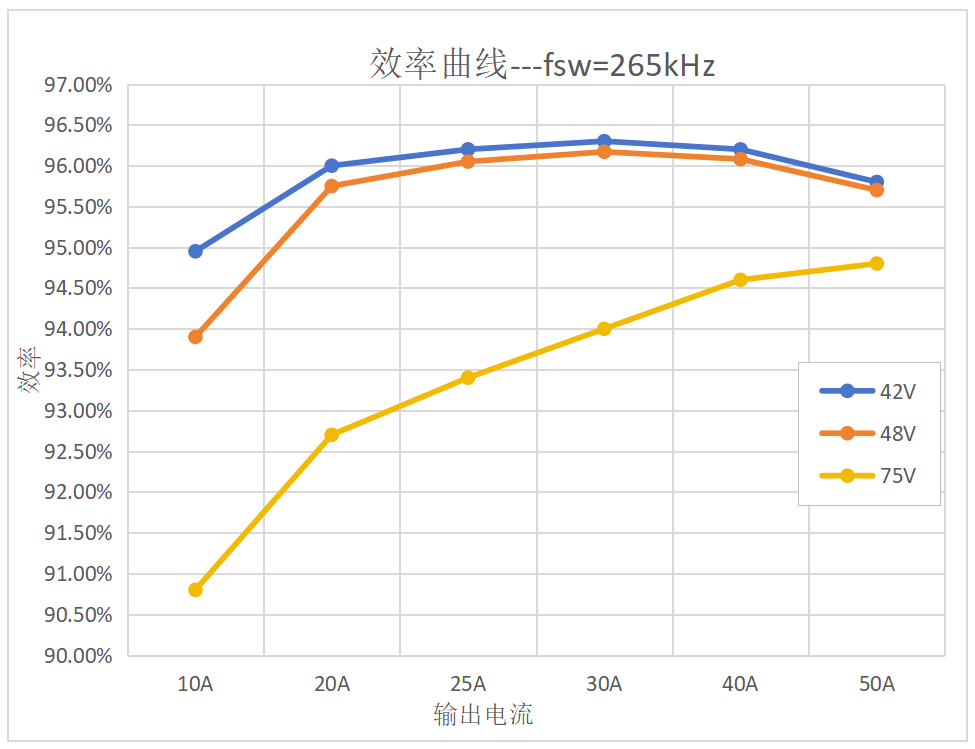
Figure 15: Efficiency Curve
Below are additional performance test data for the HP1000 600 W 1/4-brick module full-bridge converter:
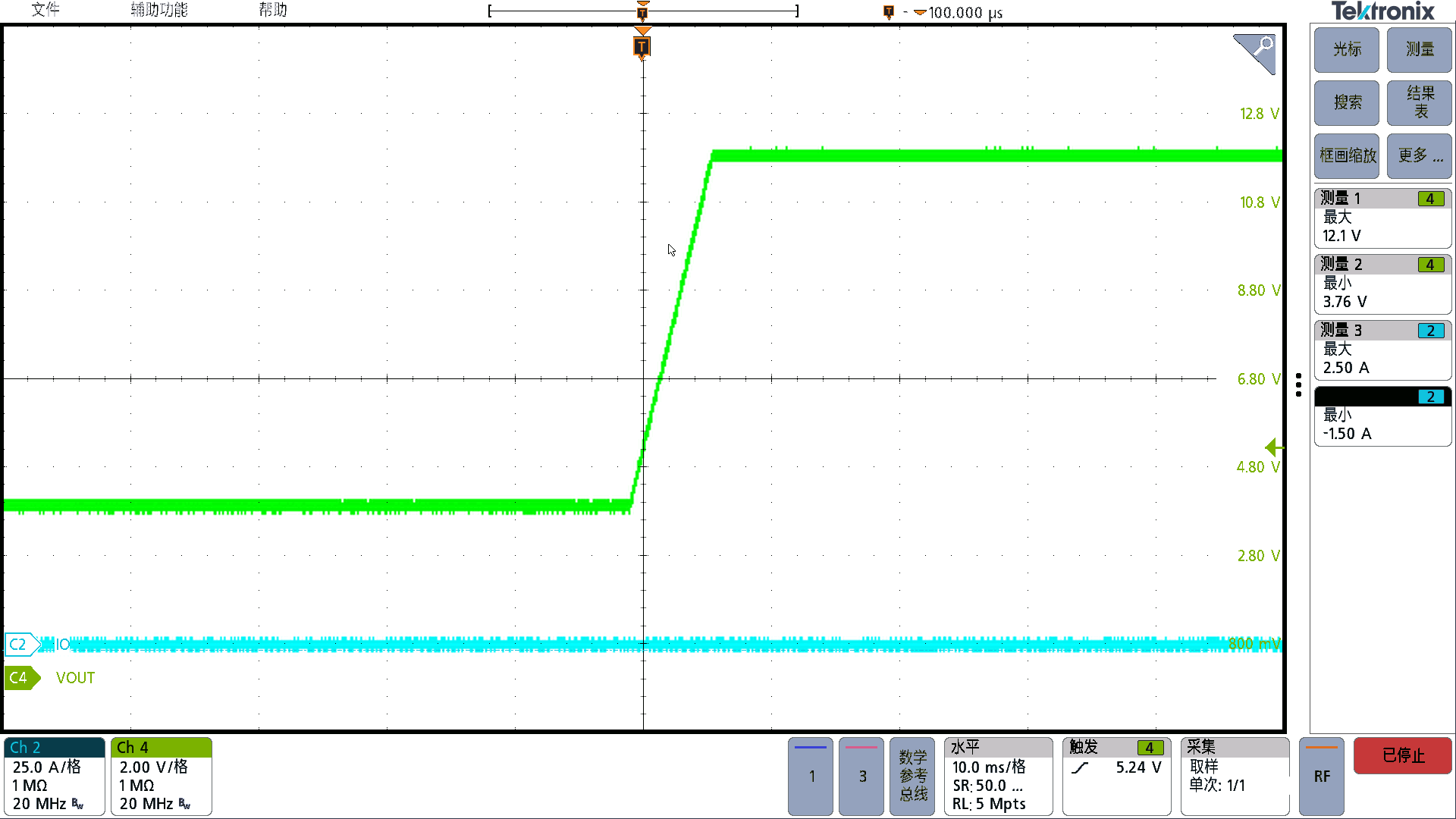
Figure 16: Vin=48 Vdc, Io=0 A---Normal Temperature Pre-bias Startup
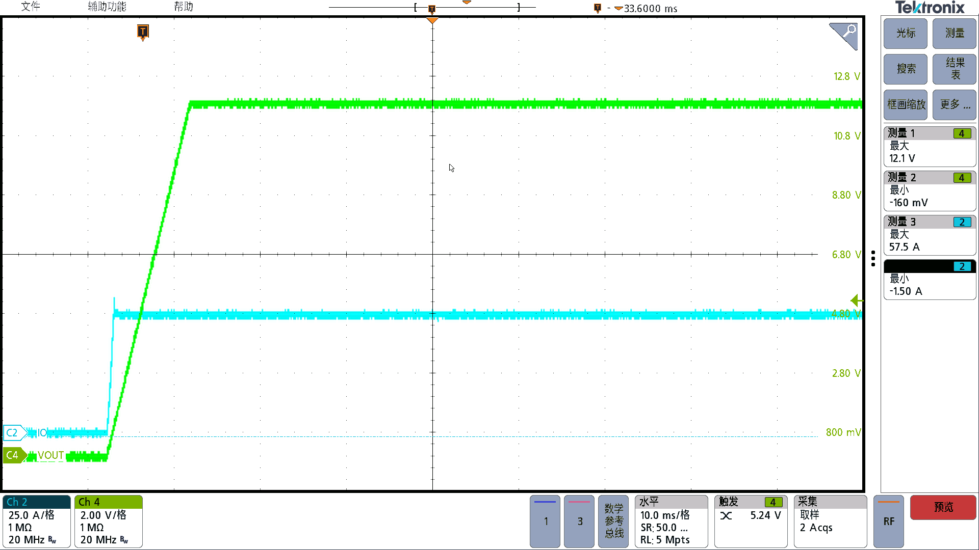
Figure 17: Vin=48 Vdc, Io=50 A---Full Load Start-up at Ambient Temperature
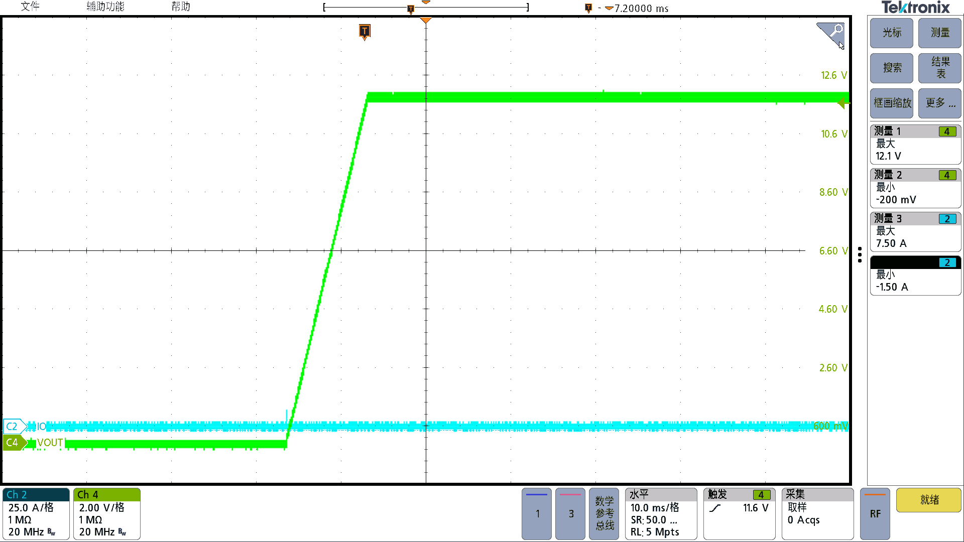
Figure 18: Vin=48 Vdc, Io=0 A---Cold Start at Normal Temperature
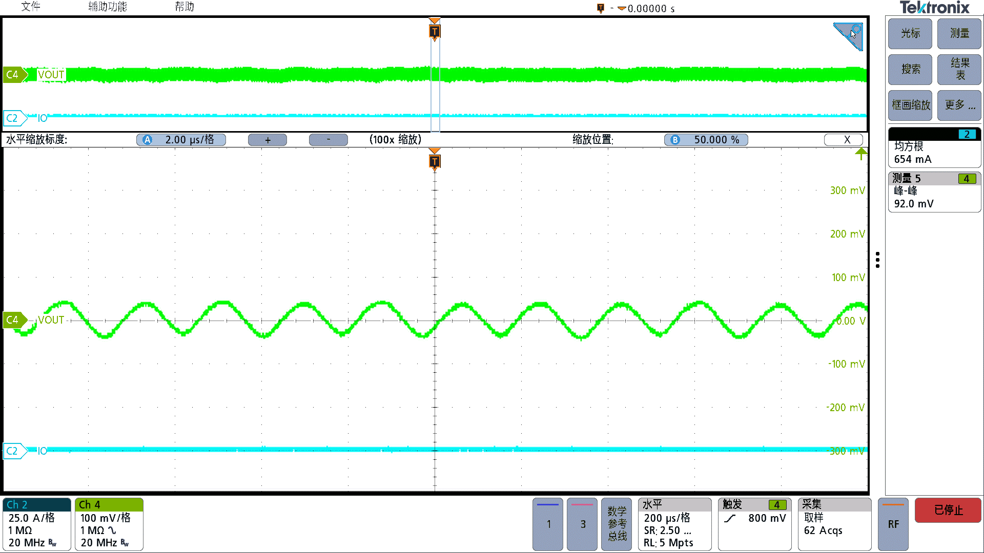
Figure 19: Vin=48 Vdc, Io=0 A---Ripple at Room Temperature with No Load
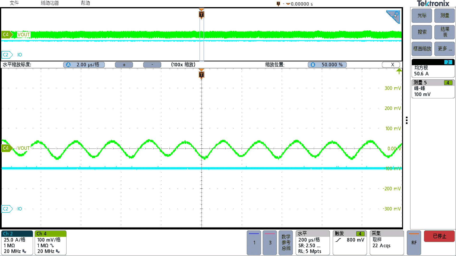
Figure 20: Vin=48 Vdc, Io=50 A---Full Load Ripple at Room Temperature
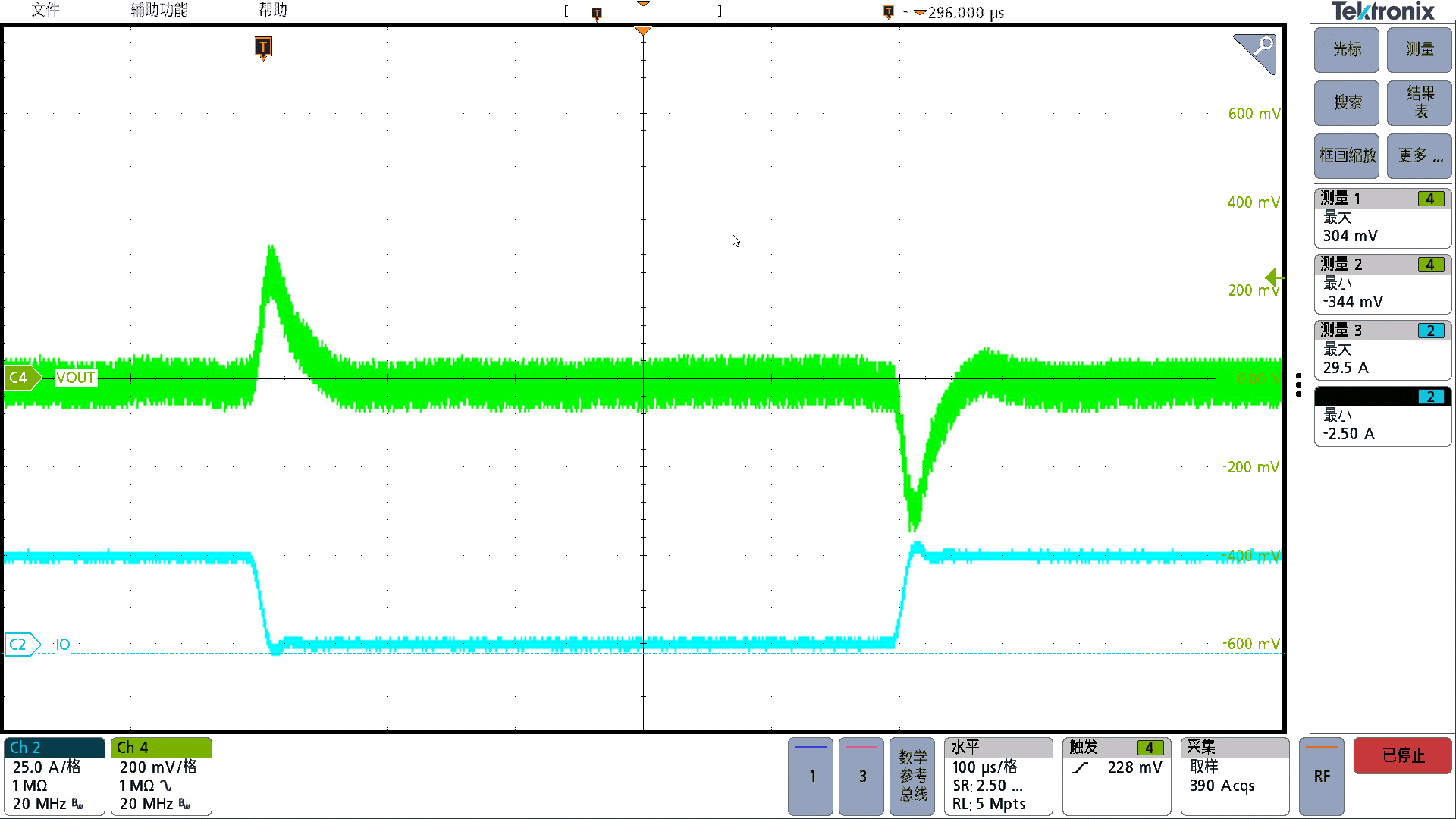
Figure 21: Load Transient, Input Voltage 48 V, Output Current 0 A to 25 A, Load Slope 2.5 A/μs
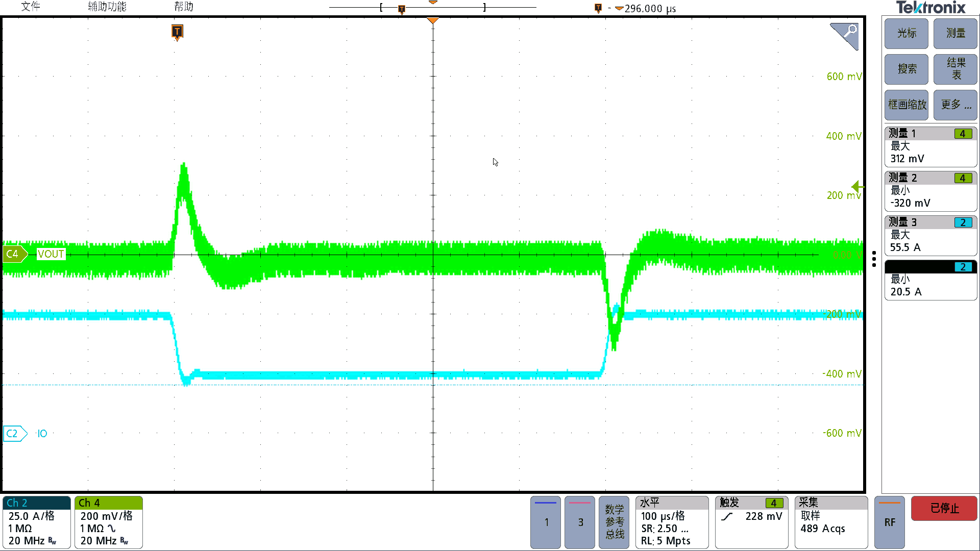
Figure 22: Load Transient, Input Voltage 48 V, Output Current 25 A to 50 A, Load Slope 2.5 A/μs
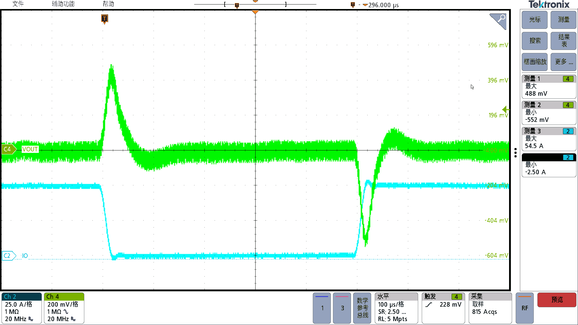
Figure 23: Load Transient, Input Voltage 48 V, Output Current 0 A to 50 A, Load Slope 2.5 A/μs
From “adequate” to “exceptional,” the HP1000 makes power supply design simpler, more efficient, and smarter!


